Basic theoretical knowledge of inverter
For more than 20 years, frequency converters (VFD, also known as variable speed drives-VSD) have been used in various applications. These applications include single-motor driven pumps, fans and compressors, and highly complex multi-drive machines. (This article includes the types of VFD, the advantages and disadvantages of VFD as a tutorial)
The function of the VFD is to adjust the motor speed to better meet the requirements of the drive load. The result is better process control and reduced energy consumption. The VFD system is quite expensive, but provides excellent control over plant operations. In most cases, the consequent reduction in energy costs and installation of VFDs are sufficient to offset (if not fully paid for) the high initial costs.
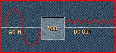
The VFD converts AC power from the input power source into DC voltage. The VFD may also include a control mechanism through which it communicates with the motor and the driven load remotely.

The control mechanism facilitates the connection of electronic equipment to monitor load speed, start and stop motors, and perform various other functions to more effectively meet process requirements.
There are currently three different VFD design types on the market. In theory, the main difference between these VFDs lies in their rectification type that converts AC power to DC power.
The most common centrifugal load applications using frequency converters are pumps, fans and compressors. The most common constant torque load applications using VFD are positive displacement pumps, gear pumps, reciprocating pumps, conveyors, extruders, extruder cutter cutters, mixers and reciprocating compressors. The main considerations when choosing a VFD are:
The nature, cost, and operating environment of the application.
VFD has many basic uses, as a special process control, not common in other types of variable speed control. When energy saving is the main goal, VFD is best suited for centrifugal loads. Due to its flexibility in automatic process control systems, VFDs are also often applied to constant torque loads. VFD is very sensitive to applications, so the compatibility of applications must be thoroughly analyzed before choosing a VFD.
I. Voltage source inverter (VSI) frequency converter
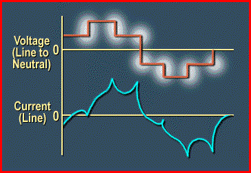
VSI or variable source inverter is the earliest solid state VFD. Because of the voltage sent to the motor, it is sometimes referred to as a "six-step" drive.
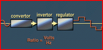
The operation of the variable source inverter is relatively simple. Basically, the AC input voltage and frequency are converted to DC by the rectifier, and then converted back to AC through the inverter part to generate the required voltage and frequency to meet the voltage ratio per Hz of the VFD output.
The advantages of VSI include good speed range, multi-motor control of a single unit, and simple regulator design.
Some disadvantages include:
As the speed decreases, the power factor decreases, induces harmonics, and directly starts/stops the action.
If you carefully observe the displayed waveform, you can see how the "six-step" power causes the cogging effect.
II. Current source inverter (CSI) frequency converter
Current source inverters, also known as current-fed inverters, behave like constant current generators, producing almost square wave currents. Due to its simplicity, regenerative capacity, reliability and low cost, current source inverters are used instead of variable source inverters for large VFDs of approximately 200 horsepower.
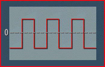
Although more robust and reliable than VSI, CSI has a poorer power factor at low speeds and is not suitable for multi-motor operation. Another disadvantage of CSI is the "cogging", jerky start/stop motion or impulse axis during operation. Careful inspection of the CSI output voltage waveform can see how this happens.
III. Pulse width modulation (PWM) inverter
This type of VFD's unique method of creating a variable voltage gave the PWM VFD a name. Pulse width modulation or PWM VFD can provide constant voltage hertz ratio, wireless circuit notch and motor very stable current input.
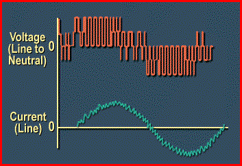
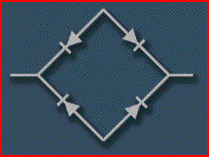
The pulse width modulation converter part uses a diode bridge to rectify AC power instead of an SCR bridge. Since the input of the inverter section is constant, the inverter controls the voltage and frequency. The semiconductor switching mode is used to convert DC power to AC output. These semiconductors may be transistors, GTO or SCR.
Basically, the main advantages of using pulse width modulation instead of voltage or current inverters are high efficiency, constant power factor, regardless of speed and no cogging issues.

Other advantages include wide speed range, open circuit protection and multi-motor operation.
In terms of disadvantages, PWM requires additional hardware to realize the line regeneration capability, the equipment is more complicated, and some PWM units will produce obvious audible noise.
Advantages of variable frequency drives
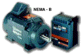
VFD realizes the most common motor in the industry, the standard squirrel cage NEMA B induction motor. Using standard motors means that VFD is not only suitable for new applications, but also for retrofitting old existing motors. All types of AC speed controllers are compatible with standard motors.
In several respects, VFD contrasts sharply with other variable speed controls. The main reasons that VFD is more ideal than other types of variable speed control are: energy saving, improved process control, reduced system maintenance, bypass capability and multi-motor control.
1. Energy saving
VFD is by far the most effective type of speed control, especially when used with centrifugal pumps and fans. When applying VFD to centrifugal pumps or fans, the load characteristics are restricted by the "law of affinity". These laws state that speed is proportional to current. Torque is proportional to the square of the speed change, and horsepower is proportional to the cube of the speed change.
When plotting the horsepower curve, it can be seen that when the speed decreases, the horsepower required at a given speed drops very quickly. The horsepower requirements of other types of speed control will also be reduced at reduced speeds, but not lower than VFD.
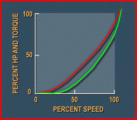
The difference in horsepower requirements at a given speed between a VFD and any other type of variable speed control is that the VFD provides greater energy savings. This is one of the basic advantages of VFD.
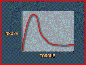
The inherent characteristic of AC VFD is that it acts like a step-down starter. In other words, it will limit the amount of inrush current. A motor started across the line will draw about 600% of the inrush current. The VFD limits the inrush current to 150% of the maximum value. The power company will provide inrush current when starting the motor. This is called the demand cost. Limiting the amount of inrush current in large motors can save money by reducing demand costs.
2. Improve process control
One goal of most factories is to automate their processes. The key aspect of automation is better communication between plant instruments. AC VFD is a solid-state device that is very suitable for process control networks. These VFDs receive process control signal inputs for start/stop, speed control and output signals. Then the signal is transmitted to the DCS system, PLC system or back to the personal computer. Other types of speed control are usually limited (if not completely absent) by these interface capabilities.
3. Bypass capability
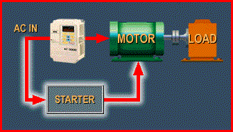
When a critical application requires a backup control device, it is easy to bypass the VFD. This VFD bypass starter in parallel with the VFD allows the bypass mode to be completed in a few seconds. Other types of variable speed control are physically coupled with the motor and load. Whenever the speed control device fails, it must be decoupled, repaired and reinstalled. The VFD is bypassed in a few seconds, while other types of speed control and its applications may be down for hours or even weeks.
4. Multi-motor control
In theory, a single VFD has the ability to control multiple motors. Other types of speed control cannot provide this possibility. The smaller physical size and lower initial cost of the VFD system are additional advantages.
5. Reduce system maintenance
The use of VFD significantly reduces the maintenance of the entire system. This is especially suitable for mechanical design systems such as eddy current clutches and variable pitch bale applications. VFD helps reduce the wear of belts, pulleys, gearboxes and couplings. All of these usually cause serious maintenance problems due to wear caused by very corrosive or other harsh materials.
The VFD does not turn the motor on and off, which is common in other processes. The VFD just slows down the motor and load in order to strictly follow the specifications. By eliminating the cyclic process, the VFD can eliminate troublesome surges and torque pulsations in the entire operating system.
Disadvantages of variable frequency drives
1. Initial cost
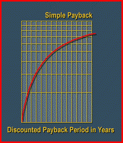
The initial cost of a VFD is usually higher than other variable speed controls. In fact, the initial cost is usually the main obstacle for process plants wishing to install a VFD. However, the basic energy-saving investment recovery time and process control enhancements of these VFDs are not just about the rationality of investment. There is one exception; if the average throttle speed requirement for a given application is low, between 90%-100%, the return is usually not significant. As a general rule, the estimated maximum return interval of 2 1/2 years will limit the purchase of VFDs.
2. Maintenance skill group
Objections to the purchase of solid-state design equipment usually come from maintenance personnel.
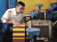
For experienced maintenance workers, the mechanical device will obviously not cause diagnosis or other problems. A cursory inspection is enough to see if and why the equipment is malfunctioning. Like any solid state device, VFD requires special troubleshooting practices and theoretical knowledge. The diagnostic capability of VFD is significantly improved. This requires additional, usually perennial training for maintenance personnel who are not familiar with solid-state design technology.
3. Low speed overheating
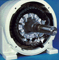
For constant torque applications, the motor may overheat during low speed operation. Regardless of the motor's operating speed, a constant torque load will consume the same current. This can cause problems at extremely low speeds because the VFD reduces the motor frequency to reduce the motor speed. If the motor generates high heat when running at low speeds, it will cause overheating.
According to experience, a fully-loaded motor with Class B insulation running at 50% of the rated speed under a constant torque load will not overheat. If the motor runs continuously below 50% speed, it will overheat. Basically, the speed of a fully loaded motor with class F insulation can be reduced to about 20% of the speed without overheating. The lower the continuous running speed is below the motor's hot spot, the more the motor and VFD must be derated.
4. Output harmonics
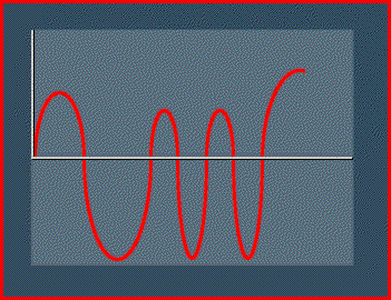
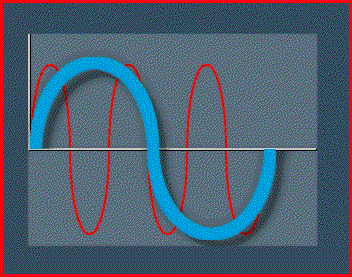
The output waveform generated by the VFD is a non-linear waveform. This waveform produces harmonics in the motor. Harmonics are multiples of the fundamental frequency and current components. The current component generates heat in the motor. According to experience, compared to the same motor running on the sinusoidal waveform of the power line, the heat generated by the VFD in the motor increases by 5% to 8%. The solution to this problem is to use class F insulation, frequency converter rated motor.
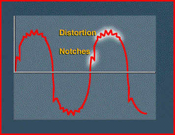
5. Induced harmonics-distortion and line notch
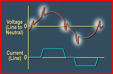
VFD is a non-linear load, it will cause harmonics of the power line. The two aspects of harmonics are distortion and wire notch. Distortion is the result of the non-sinusoidal waveform produced by the VFD. This is used to draw current from the power line in the form of non-sinusoidal pulses.
The line notch is caused by the VFD with SCR rectifier. When the SCR fires continuously at a specific point on the AC waveform, the harmonics will include switching back to the power line.
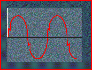
These can severely distort the power cord and, if not properly protected, may hinder the operation of other devices on the power cord.
All VFDs with silicon controlled rectifiers (including AC and DC) should include an isolation transformer or a line reactor at the input of the VFD to protect the power supply from excessive distortion.
Comments
Post a Comment